Originally when I build layers for version 5 some of the blending effects in DAP layers got (let’s call it by a mistake) reversed from how they behave in Photoshop. I simply didn’t compare what the same effects in Photoshop does. This wasn’t big deal when you use it all in DAP, until now when I added PSD export and realized that some things don’t looks correct in Photoshop. It affected only 5 non-symmetrical color modes where the order of layer matters most.
It is too late to change now so a new mode was added: PSD compatible mode that is ON by default on any new Layers in version 6 but off when you load presets.
That means if PSD Compatible Mode is OFF (then it works just as in version 5) and what you see on the screen may not appear the same way exported (Save PSD) in Photoshop if certain blending modes are used. The affected blending modes are mainly: ColorDodge, ColorBurn, VividLight, LinearLight and Pin Light.
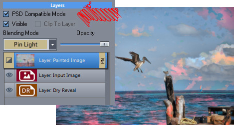
To better illustrate the issue, we use “Reasure” layer preset from version 5. This preset uses Painted Image on the top and blend it with Input image below it using Pin Light mode to get subtle color effect from the input image. All is fine, until we export it to PSD as it will appear rather very different in Photoshop. Instead of input image lightly affecting the painted image it is the other way around, the painted image lightly affect the input image.
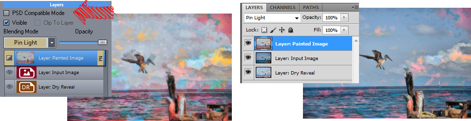
Now you see it is all wrong. The layers are in the same order, the modes are the same – but it looks different.
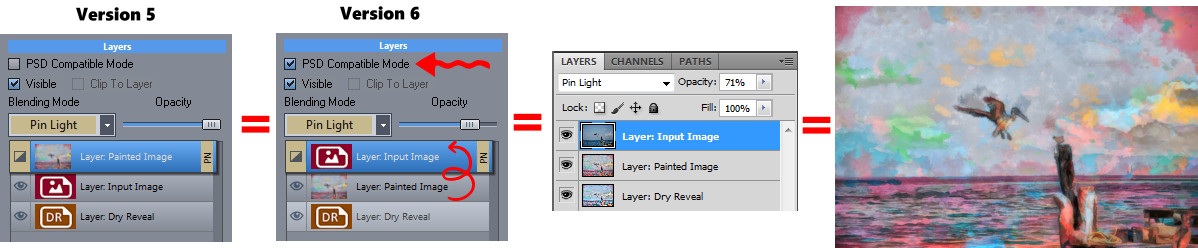
When you set the PSD Compatible Mode in version 6 to ON, DAP will mimic the Photoshop style blending and the image in DAP will then appear the same as in Photoshop when you export them:
Fixed?… Well not entirely.
The DAP layers and PSD exported layers have now the same look which is cool but sadly it isn’t actually the effect we originally wanted – it is reversed. In order to change version 5 preset into PSD Compatible version 6 you need to set PSD Compatible Mode and also swap the two affected layers – the Blending layer and the layer below it. However just swapping them is not enough, you also need to switch their blending modes (so the Input Image will be now on top and have Pin Light mode set and the Painted Image will be below it with Normal Blending)
The presets are still in v.5 mode so when you load preset the checkbox will be set to off. At some point I should change the presets also to PSD compatible mode.
Quite a lot of people are using DAP as a preparation tool for real paintings. And I am not exception and used DAP occasionally to simply “pre-chew” a boring photo into something paint worthy.
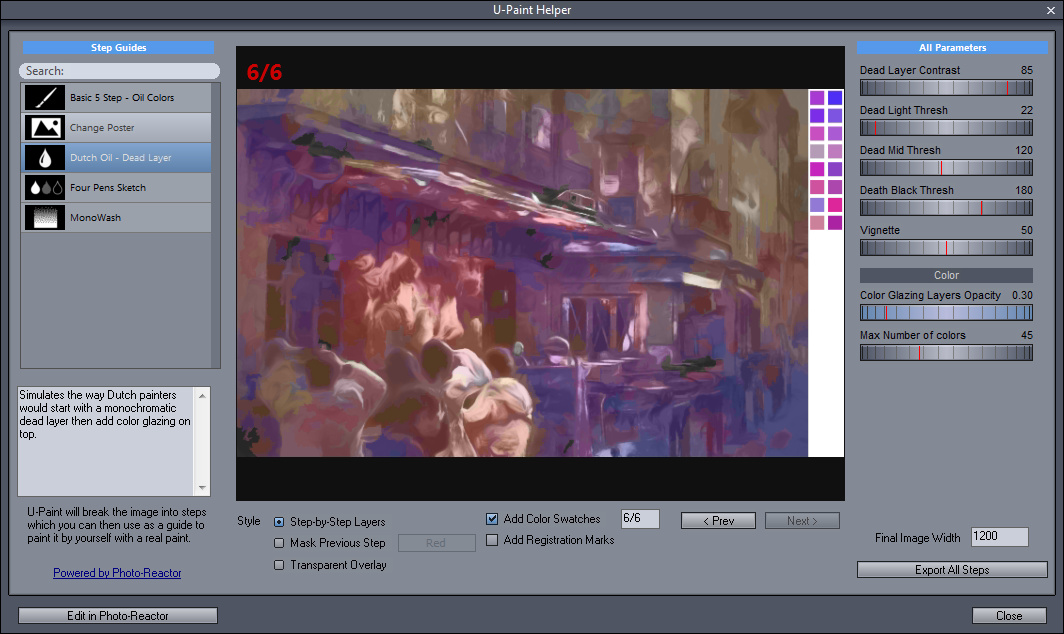
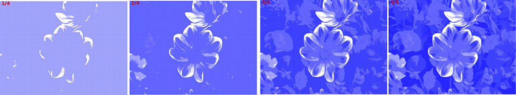
The idea of U-Paint is that it breaks image into various steps and layers that can be helpful for real-world painting. For example I often want to see the values (something called zones in photography) which is a stepped grayscale version.
U-Paint is driven entirely by reactor and it creates a series of images that you can then export and use for painting (we are talking about real painting here). You can have it display in various ways as a step by step cumulative display where next step will just add on top of previous steps, as a mask previous step – where stuff that had been already painted will be masked out with a color, or as transparent stackable layers.
This of course all depends on the reactor file to return the correct images – which are basically like the last option – a series of transparent stackable overlays.
There are few reactor preset supplied and I am planning on making more. For example we can look at the Mono Wash which is probably the most obvious. Imagine you use single thin watercolor paint and then paint first very light layer of a light shades, let it dry, paint next layer of darker shades on top etc…
And Indeed I actually painted this way more than once. There are other Reactor presets that try to break down a color image into groups of colors by either hue or simply start painting in blocks and then refine the blocks further with smaller details.
If you have Reactor installed you can look at the insides. but be warned – it is messy. You also need to have Reactor 1.8 or newer.
So how do you create your own U-Paint Helper VFBOX file?
Each step is in general a transparent “overlay” that when stacked will produce the final image. (May not be always true)
But it doesn’t mean it had to be that way. You can have steps anything you want – they don’t need to stack or combine into a picture. The final reactor flow is then saved as vfbox file and put into the User Documents\DAP\upaint folder. (When you are editing directly from the DAP interface, this will be all done for you)
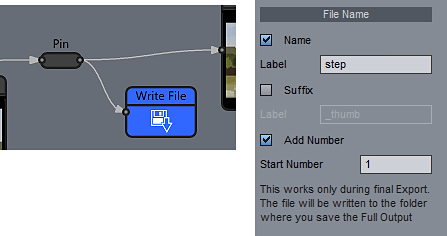
Each step is generated by attaching Write File Block where appropriate. The Write Block needs to have Name: “step” and also set “Add Number” which will then became the step number (make sure you don’t have gaps in numbering).
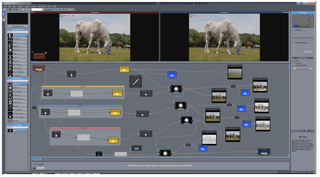
Note: In the new reactor you may find few interesting things if you have Photo-Reactor 1.8.1 and newer like the image below.
The first thing is there are straight lines with a number. This is called “Beams” and it simply connect an object to the same node number somewhere else with a thin straight lines without making all the wormy connecting lines. Sort of like a portal. Right click on the object, select Line Draw and there it is.
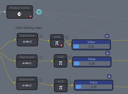
Second thing is the sliders are blue and have an “A” to them. This is called a “Group Link” and it means when you move one slider, all of them having the same “letter” will move as well. This translates to the VFBOX parameters as well. And that is the third thing -an object which has any of its settings present in the Parameters (parameters that will be visible in VFBOX) has a small red dot. Well if any of the linked parameter of object (such as our “mult”) has a slider attached to the parameter and that slider is set in a group link, moving the parameter in VFBOX file (for example inside DAP) will ultimately change all the other linked sliders and parameters (in our case – all the “mult” objects).
To change the group link – click on the slider and look in the right hand properties – there should be a combo box where you can set the group “letter”. This works for slider and a knob.
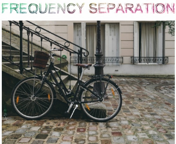
You may have already heard about Frequency Separation technique in photo editing, since it became popular in the past few years.
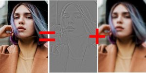
In short you separate your image into two parts: High Frequency that contains the texture and fine details and the Low Frequency that contain colors and tones and rough details.
This way you can focus your editing on just the texture or the tone and not being concerned with both at the same time.
Sounds pretty cool. So how to do it in Photo-Reactor?
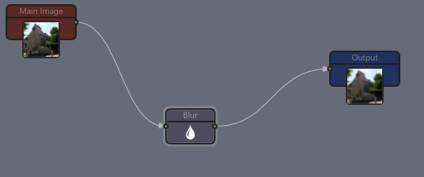
The low frequency is generally just a blurred image with Gaussian blur. That part is easy.
But how do we get the High frequency component?
We don’t need to re-invent the wheel. The High frequency is the rest what was removed by blurring! Or to formulate it another way: it is the difference between the original and the blurred (low frequency) image and this is pretty much how Photoshop (or Photo-Reactor) High pass filter works.
We could do that with the reactor objects alone, but to keep things short and fast, we will use just a single reactor C++ block and type a short code that will do that part for us.

Remember the reactor c++ script needs also the first comment lines (the //## ) that will setup the number of inputs and variables for the block. Once you copy the code and press compile, the block will have two inputs and a slider.

If you do this right, the output will show High pass image and when you change the Blur radius, it will work exactly like the radius in High Pass filter in Photoshop.

We added one variable “Multiplier” to the object. By default it should be in the middle (50) and that would produce the High Frequency as the exact counterpart to the Blur (Low Frequency). We can use this slider later for experimenting to add or remove the High Frequency.
How to tie all this together?
The output from the Blur block is the Low Frequency, the output of the C++ block is the High Frequency. So how do we merge them together back. Luckily there is Linear Light blend mode, that will do all that for us.
In this configuration as on the picture the Linear Light blend object need to have Swap layers to apply it correctly, or you can just wire the Blur to A and C++ to B.
If everything is right, then the output should be now the same as input. If it isn’t check if you have Swap Layers set on the Linear Light.

So after all this we produced exactly nothing as the output looks the same as the input. But that is the proof that it works we needed! We separated the image into two frequencies and then merge them together.
The Blur Radius determines the Split point between the frequencies and we can drop a Log Knob on the Blur object to extract that value to the workplace for easy manipulation.
Having a single split point is also the reason why we didn’t just use the build-in High Pass filter that exist already in Photo-Reactor. We really want the High frequency leg to be the exact counterpart of the low frequency. Regardless where we put the split point (Blur radius) the result image will be still same as the input even though both low and high pictures will change dramatically.

So it is now entirely up to you how to use it. I dropped few pins so I can easily connect objects in the path between them.
For example I can add Median or Noise reduction to the High Pass path and Saturation to the Low pass… but it can be as complex or as experimental as you want.

There are many uses, for example we can soften skin on portraits without changing the tone. Or we can do crazy things. But I leave it for you now.