Windows 7,8,10 (5MB)

THE ULTIMATE SOLUTION FOR WINDOWS MACROS


Version 2.28
Project 2 - Rotary Dial: Reusing existing controller
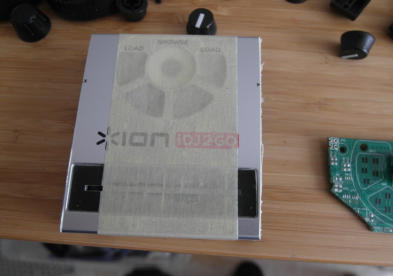
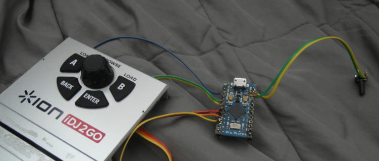
This is a continuation of Project 1 After some testing the Arduino project breadboard, it turned out to be pretty reliable solution. Instead of creating a box for the project, in this second part I am going to reuse an existing controller to host the arduino board and create something almost semi-professional looking. Almost. This little gadget bellow was found in a thrift store. for a few bucks. It ended up there because it likely became obsolete in a short amount of time having the old iphone 48 pin connector. I am not even interested in testing it if it works on my old iphone. Regardless if it is broken or not, for people like me it is a treasure of parts and components for a project.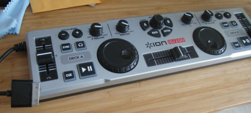
Initial examination:
I have particularly my eyes on the middle part. The center knob is obviously an ordinary rotary
encoder which means I should be able to just swap it in my Arduino project as it is.
The large rotation knobs on the sides spin freely (no detents) so they are likely optically sensed
rotation encoders.
Other knobs are just potentiometers. It would be very hard to find some task for a potentiometer to
simulate a keyboard keypress.
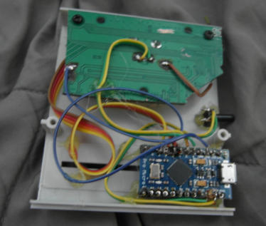
The controller is thick enough to host the Arduino Pro Micro somewhere after I liberate it of its PCB.
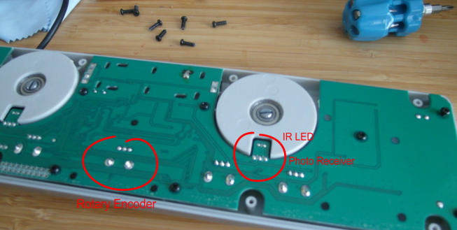
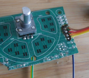
After opening I see in the middle we have indeed and ordinary rotary
encoder. The knobs on the sides are optically sensed encoders. It would be
possible to use them as well - but it would require much more time and
work - I would need to first research the parts used and then see how it can
be used in the arduino and/or perhaps put an amplifier for the signal.
However my idea is to have an hour long project and that would not work
then. Still, I will keep them in my drawer for some future projects.
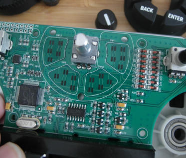
The middle part has 4 button pads, that we can reuse as well. The pads very visibly trace to the diodes on the right side
of the PCB, this would be great place to solder wires. When arduino inputs are set as weak pull ups, those graphite
pads would work very well when one of the pole is ground. The slider below the buttons will have to go as well. If there
was more space, I may think of some funky two key flip switch (for example firing CTRL+C on left and firing CTRL+V on
right side) but I will use its space for the arduino micro. Maybe some other time.
Let’s get a hacksaw…
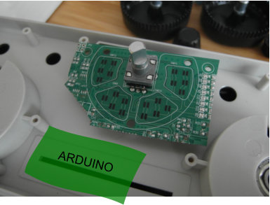
Cutting the PCB, making very sure the traces for pads are not
cut somewhere by accident.
Chopping off the sides from the plastic enclosure as well.
Attaching wires to the pads.
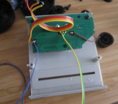
The blue wire is ground that is also attached to the middle pin of
the encoder. The rainbow wires are one pole of the pads. All
pads have one common trace that joins all the pads, and I need
that to bridge it to the ground (brown wire). The yellow and green
are data for the encoder. That’s about it.
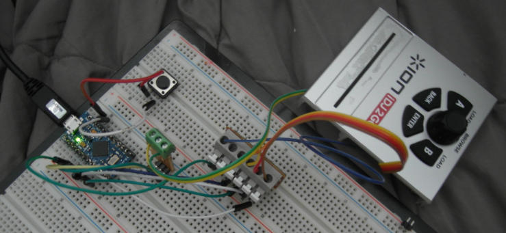
Let’s replace the kit encoder from Project 1 with the new encoder from the ION. I will need to add more code for the
additional buttons. After quick test… it WORKS!
It always fascinate me when such a low-fi hack job works on a first trial.
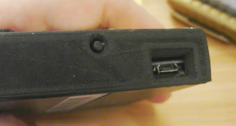
Since all seems fine on the breadboard, now I will directly solder the wires to the arduino. I also need to have reset button since
the Pro Micro is missing one and this particular arduino is impossible to program without reset button (see more in Project 1)
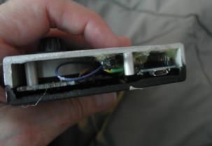
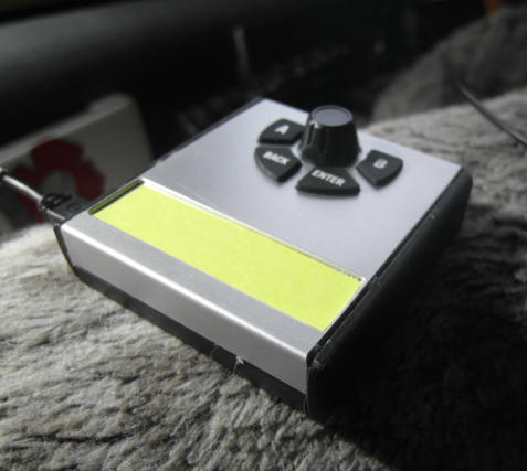
After another test, it is time to put it all inside the box itself. A
heat gun is my friend here. It can attach anything to plastic.
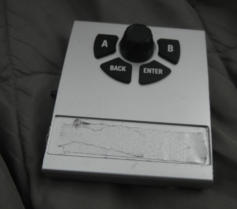
Before everything goes permanently in the box, I quickly took one more time to dissemble it
and a swiftly spray the face plate with a spray color.
It doesn’t take very long to dry if sprayed only very lightly.
The sides are still pretty rough looking. Now it is time for my other favorite hobby beside
programming: 3D design and 3D printing.
Originally I was planning to put a wooden sides, but let’s be honest, it is much faster to just
design the sides in CAD in a comfort of my office and have them then 3D printed while I am
having a coffee.
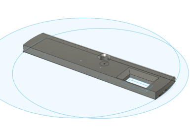
Quick design in Autodesk Fusion 3D of the sides.
Just a measure here and there with a digital caliper
and put it down in CAD
With Fusion it is job for 5 minutes max.
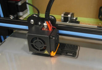
Then wirelessly send it to the 3D printer in basement.
30 min later while I drink a cappuccino the sides are
finished.
I am using glue gun yet again to attach the
sides to the whole mouse trap. Gluestick when
used on PLA will allow me to disassemble it
when needed.
Everything lines up, 3D printing is precise to a
fraction of millimeter - it all depends how well I
measured where the holes need to be with
caliper… and I seem to got it right.
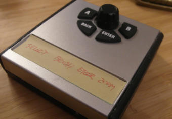
A little post-it paper on the face plate can be
used as a note
Arduino PRO Micro Sketch
Here is the sketch for this version. The difference is support for multiple buttons.
The rotary encoder is mapped again to [ and ] and the buttons are mapped to some common Photoshop keys. It is not crucial, because with MultiKeyboard Macros everything can be
remapped later.
The code above is non-blocking which means there are no delay commands (which I find a bad and amateurish idea) It also uses interrupts to capture the encoder. After testing it for some
time, I am quite satisfied how the code naturally debounce the buttons and encoder and how reliably it works.
Generally making the knob bigger would be preferable, which is not possible in this case due to the used buttons around the knob.

Get Updates


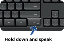
Ultra fast voice typing and voice commands - processed
entirely on your PC, in any application, forever.
No cloud. No monthly fee.

If you like Multi-Keyboard Macros - try our new Voice Macros!


About MediaChance
Products
Links